|
|
|
Low Voltage Lamp Developments |
|
Introduction
The origin of the sodium vapour lamp may be traced back to a 1919 patent taken out by Arthur H. Compton of Westinghouse Electric in the USA. This was the first light source which radiated the characteristic deep yellow sodium resonance lines (Compton, 1919). The mercury lamp had been in existence for nearly twenty years but sodium also made a logical material for a vapour lamp, quite simply because it has a relatively high vapour pressure. Compton had noted that the sodium discharge delivered a remarkably high luminous efficacy of more than 200lm/W, although this figure did not include the power required to heat the lamp to its operating temperature (Compton and van Voorhis, 1923).
At this stage it is appropriate to explain the term efficacy - it is the ratio of the total light output (lumens) to the input power (watts). The units are lumens per watt, lm/W. As a comparison, tungsten filament GLS lamps have an efficacy of about 13 lm/W. Efficiency, by contrast, refers to the absolute power in watts that is emitted as light expressed as a ratio of the wattage consumption of the lamp. Efficiency does not take account of the human eye's varying sensitivity to different colours of light as the lumen does, so efficacy is a more useful term to the lighting engineer.
|
Westinghouse Lamp Design
Efficient as Compton's lamp was, it could not be commercialised owing to the highly corrosive nature of heated sodium. No glass was available at the time which could contain the discharge without very rapid deterioration. Westinghouse therefore directed Compton's attention at creating a suitable containment, and the following year he patented a borate glass which offered considerably enhanced resistance to sodium vapour (Compton, 1920).
In 1920 Compton made the first successful sodium vapour lamp based on this glass, and its appearance is illustrated schematically in Figure S16. It consisted of a section of borate glass tubing which had been blown to an approximately spherical shape at the centre, and a coiled tungsten electrode was sealed into either end of the discharge vessel. The electrodes were brought to incandescent temperatures whereupon thermionic emission took place and they formed good cathodes, and a discharge could then be struck across the gap. The distance between electrodes was relatively short and the lamps therefore had a low operating voltage, and a high current was necessary to deliver a useful amount of light.
|

Figure S16 - A.H. Compton's Low Pressure Sodium Lamp of 1920
|
Osram Experimentation
It was not until 1930 that significant progress was made, when M. Pirani of the German Osram company began to experiment with sodium discharges. He created a series of low-voltage high-current tubular lamps which were operated in ovens to vaporise the sodium to the required pressure, and with a sodium vapour pressure of 10Pa in krypton-filled tubes measured discharge efficacies as great as 350lm/W (again not including the power supplied by the oven to heat the lamp). The first practical sodium light source was created following Pirani's work, and following a trial in one of the inner courtyards of the Osram buildings in Berlin, he lit one of the streets outside in August 1931. A glass sleeve around the discharge tube effected some crude thermal insulation to keep the discharge hot enough to vaporise enough of the sodium, and these lamps delivered an efficacy of some 46 lumens per watt.
|
Philips Developments
The first company to commence manufacture of the sodium lamp was Philips, and the earliest commercial application was made with 'Philora' lamps on the 28th June 1932. Thirty direct current lamps were installed on a section of road between Beek and Geleen in the Netherlands, and Figure S17 illustrates the type of lamp that was employed. They were driven at 15V 5.5A and attained a system efficacy of 38.5lm/W (including the transformer losses and electrode heating current). A single central cathode was mounted at the centre of a large diameter glass bulb, the cathode being coated with alkali-earth oxides for good electron emission. The discharge was struck to a pair of anode rings at opposite ends of the discharge vessel some 2cm either side of the central cathode, and the whole assembly was enclosed in a detachable dewar jacket to maintain the lamp at its high operating temperature. Lamps had to be operated in DC circuits because it was found that their life was unacceptably short when driven from an alternating current supply (Dorgelo and Bouma, 1937). This is because on DC, the sodium remained around the cathode at the centre of the bulb, whereas on AC it could migrate to the tube ends when they were in the cathode part of the cycle, and the sodium would then attack the glass at the end seals.
|
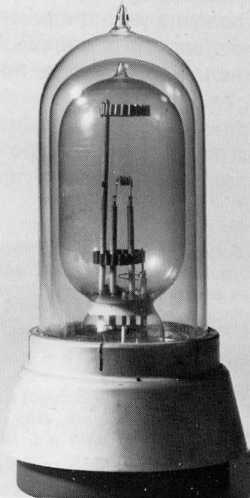
Figure S17 - Philips Philora DC, the first commercial sodium lamp of 1932
|
General Electric American Design
Following on from Philips' development of the DC lamp, GE of America promptly adapted the design for AC operation and its famous 10,000 lumen 'NA-9' sodium lamp was placed on the market in 1936 (Figure S18). It had an oxide-coated heated electrode at either end of the discharge vessel (Buttolph, 1939), and was manufactured in the USA without change until 1966. Before starting, the cathodes required an excitation current of 10A at 2-3V to bring them to thermionic emission temperature, and a mechanical relay then applied the full open circuit voltage across the tube and the arc was struck in essentially pure neon. Lamps were operated in series-wired strings with the discharge current being limited to 6.6A at 50V, falling to 30V over a thirty minute period as it warmed up. The total wattage was 180W per lamp. A smaller 145W 6,000 lumen rating operating at 5.5A called the NA-10 was also produced by GE, although that size never became popular. Additionally there was a small 65W NA-1 lamp, having a very small discharge tube and being intended as a laboratory source of monochromatic radiation.
GE's effort was somewhat inefficient and rather short-lived (3000 hours) by contrast with simultaneous developments that were taking place in Europe, but GE still marketed this antiquated design until the company had perfected its high pressure sodium light source. It is interesting to note here that to circumvent patents relating to the borate glass that was required for sodium lamps, GE developed a different approach to protect the glass in its NA series light sources. The large discharge vessel was first fabricated from ordinary borosilicate glass, blown into a mould just like mercury arc tubes of the period, and then filled up with a solution which left a deposit on the inner surface of the bulb after draining out. Following a high temperature firing schedule, a borate-rich layer was fused to the inner surface of the bulb. This created a glass composition which had not been covered by competitors patents in view of the fact that such a glass is not workable (i.e. it cannot be heated up and shaped like other glasses).
Just like the Philips design the entire discharge tube was operated inside a dewar jacket to provide thermal insulation, with a stack of soft asbestos rings around the cap closing the neck area to prevent convected heat losses.
|
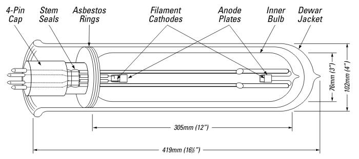
Figure S17 - The NA-9 American-style lamp of General Electric
|
Low Voltage Lamp Construction
Both the Philips and GE low voltage sodium lamps were fabricated along similar lines to incandescent lamps of the period - thus a glass stem assembly was formed, in which the leading-in wires were sealed into a glass tube, one end of which had been flared out. The rim of the flare was then fused into the open neck of the glass bulb sealing both parts together to yield the arrangement shown in Figure S18a. This created a problem, because the neck area was a long distance away from the heat of the discharge and sodium would tend to condense here and never get hot enough to be vaporised into the discharge. Shortening the neck area and bringing the stem further into the bulb was of course feasible, but that resulted in the glass-to-metal seals becoming closer to the discharge and operating at a higher temperature. Rapid corrosion of even the best borate glass then occurred and the seals would crack. The problem was overcome by two different approaches - that of Figure S18b being the ultimate Philips solution, whereas GE adopted the design in Figure S18c.
Philips pioneered the introduction of the so-called "reversed pinch" in which the pinch-seal around the leading in wires was made on the outside of the bulb. Thus the glass-to metal seals were kept at a low enough temperature to ensure reliability, but sufficiently warm to prevent sodium condensation.
GE's preferred approach, which was an earlier abandoned development of Philips, was to continue with the stem sealed design but to isolate the neck from the bulb portion. Either a chrome-iron or a mica plate separated the two regions, pierced by the lead wires which were cemented into place with a non-silicate ceramic paste. A small glass or ceramic tube also penetrated the disc, out of necessity to enable the lower volume of the lamp to be evacuated during manufacture, but the tube was so slender that virtually no sodium would pass through into the neck chamber during the lamp's relatively short life, thus keeping the aggressive filling away from the vulnerable glass to metal seals.
|
Figure S18 - a) Normal seal, b) Philips reverse-pinched seal, c) GE isolated seal
(Not yet uploaded!) |
|
|
|
|
|


