|
|
|
This article was written by fellow lamp engineer and collector Edward J. Covington, and originally appeared on his own website of biographical sketches of persons involved in the lamp industry. Following his passing in February 2017, and with kind permission of his family, Ed's words have been preserved here in the hope of maintaining access to his writings for the benefit of subsequent generations.
|
St.George Lane Fox-Pitt21 |
Biography
The name of Lane-Fox appeared along with those of Swan and Edison at the end of the 1870s and beginning of the 1880s in the technical literature and newspapers during the time when there was considerable activity aimed at producing a practical incandescent lamp and distribution system. St. George Lane-Fox (Sep 14 1856 - Apr 6 1932) was on the incandescent lamp scene for only about five years, but he deservedly earned a place in the history books.
For the purpose of clarification, an explanation of the name change of the family of Lane-Fox is in order because of the confusion it can cause for the reader. Up until the year 1880 the full name of the father of St. George was Augustus Henry Lane-Fox. In that year a cousin of Augustus, Horace Pitt, 6th Baron Rivers, died and his estate passed to Augustus, with the stipulation that Augustus take the name of Pitt-Rivers. Thus, on May 25, 1880 Augustus Henry Lane-Fox became Augustus Henry Lane Fox Pitt-Rivers. It appears that St. George Lane-Fox and some of his siblings assumed the new surname name of Fox-Pitt at the same time15. In this write-up, therefore, the full name of St. George is considered to be St. George Lane-Fox until May 25, 1880. After that date his full name is considered to be St. George Lane Fox-Pitt. However, there are inconsistencies in the use of his name by many writers; such inconsistencies certainly are understandable.
St. George Lane Fox-Pitt was a son of Augustus Henry Lane Fox Pitt-Rivers (1827-1900) and Alice Margaret (nee Stanley) Pitt-Rivers (1828-1910)29. The Pitt-Rivers had nine children, these being:27,29
Alexander Edward Pitt-Rivers (b. 1855)
St. George Lane Fox-Pitt (b. Sep 14, 1856 - d. Apr 6, 1932)
William Fox-Pitt (b. 1858 - d. 1945)
Ursula (b. 1859 - d. 1942)
Lionel Fox-Pitt (b. 1860 - d. 1937)
Alice (b. 1861)
Agnes (b. 1862 - d. 1926)
Douglas Fox-Pitt (b. 1864 - d. 1922)
Arthur Fox-Pitt (b. 1866 - d. 1895)
The aspects of the life of St. George that are considered here are only his interests and accomplishments in the area of lighting, and, specifically, the electric incandescent lamp.
Incandescent Lamp Developments
The early lamp research results of Lane-Fox can be determined in his own words2,4. However, a more complete description of his lamps and lighting system was published in 18823. That description is reproduced here in its entirety.
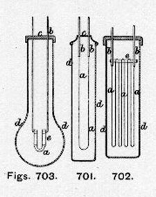
"The English patents taken out by Mr. St. George Lane-Fox in 1878, show that he was an early inventor in incandescent lighting. In that year he not only described an incandescent lamp with a platinum-iridium wick or 'burner,' and specified a complete system of distributing the currents by aid of electric mains and branch wires with current meters and regulators, but he also added secondary batteries to the circuit of the current at suitable points to act as electric reservoirs and keep the electromotive force throughout the system as uniform as possible. Mr. Fox's first lamps are illustrated in Figs. 701 and 702, and consist of glass envelopes d d enclosing loops of platinum-iridium wire, either in air or a passive gas - like nitrogen. In the figures, a a is the wire suspended from two conducting electrodes b b which pass through a cover c, which may be hermetically sealed to the envelope. In Fig. 702 the wire a is looped several times round a bar of glass or other non-conductor e, so as to give a greater illuminating surface. Fig. 703 represents another form of lamp described by him in 1878, and one which may be regarded as an intermediate form between his first lamps and the carbon filament lamp which he has now adopted. In this form the incandescent wick a is made of a refractory material, such as asbestos impregnated with carbon, and it is held by metal clips e connected to the electrodes b b, which pass through the cover c of the glass envelope d d, which is filled with nitrogen gas.
|
|
"Passing from these early and tentative forms of lamp, Mr. Lane-Fox adopted a carbonised filament in place of the wire and refractory arch or bridge shown in Figs. 701, 702 and 703, and contained in an exhausted bulb. One of the latest forms of his lamp is shown in Fig. 704, and the method of its construction will be gathered from the accompanying details in Figs. 705, 706 and 707. In Fig. 704, a is a loop of carbonized fibre connected to the platinum wires b b by small spirals c c at their ends. The connection is made more perfect by a serving of Indian ink round the joint. The upper parts of the electrodes b b are fused into solid pieces of glass d d forming the bottom of glass tubes e e containing mercury, into which the ends of the wires dip, and thus make contact with the external electrodes or terminals of the lamp f f. The tubes e e are closed at their upper ends by a layer of marine glue g, and over that a cap or luting of plaster-of-paris g1. Fig. 705 shows the glass envelope or flask A as it is first blown, with a hole at the bottom leading into the tube h. Fig. 706 represents the device inserted into the mouth of the flask to support the electrodes. It is a hollow tube of glass of peculiar shape, and bifurcated at the lower extremity as shown at e e, into which the wires b b are fused. After insertion, the bulge in the upper part and the mouth of the flask are fused together at k (Fig. 707) by the blow-pipe, and the upper piece is then severed. The mercury is then poured into the tubes e e, the stout copper wire terminals f f are inserted, and the marine glue and plaster luting cap the whole.
"It now remains to produce the requisite vacuum within the lamp, and this is effected through the tube h, which is afterwards fused in the blow-pipe, and hermetically sealed up. During the operation, which we shall describe presently, the filament is kept incandescent by passing the current through it so as to make it give off any occluded gases. The body of the flask or globe may be of any kind of clear or coloured glass to subdue or tinge the light, but the branches into which the platinum wires are fused must be of lead glass, as without the lead the platinum and glass will not readily adhere, and the glass is liable to crack through unequal expansion.
|

|
""It now remains to produce the requisite vacuum within the lamp, and this is effected through the tube h, which is afterwards fused in the blow-pipe, and hermetically sealed up. During the operation, which we shall describe presently, the filament is kept incandescent by passing the current through it so as to make it give off any occluded gases. The body of the flask or globe may be of any kind of clear or coloured glass to subdue or tinge the light, but the branches into which the platinum wires are fused must be of lead glass, as without the lead the platinum and glass will not readily adhere, and the glass is liable to crack through unequal expansion.
"Another pattern of the improved lamp of Mr. Lane-Fox, that shown at the Crystal Palace Electric Exhibition with beautiful effect in the Tropical Department and the Alhambra Courts, is illustrated in Fig. 708. Here the carbon filament a a is joined to the platinum electrodes b b by small ferrules of carbon h h, made of carbon cylinders, through which a fine hole is drilled to admit the ends of the wires. A cap or luting of Indian ink k k is then added to taper off the joints between the ferrules and the filament. The electrodes b b are fused into lead glass tubes d d as before, and the connection between them and the outer electrodes or terminal wires f f is made by the mercury at e e. Instead of employing marine glue, however, it is replaced by an elastic packing of cotton wool g, and over this is the cap or cork g1 of plaster-of-paris.
|

|
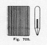
"The filament employed in these lamps is made from grass fibres, preferably that known as French whisk or bass broom, and used in making certain kinds of carpet brushes. The fibre is first cleaned by boiling in a strong solution of caustic soda or potash, and the outer skin scraped off. The soda or potash is then boiled out of it, and a number of fibres are stretched round a mould or shape of plumbago, as shown in side and end view in Fig. 709; they are then baked in a plumbago crucible at a white heat. After being baked in this manner the fibres are further carbonised by depositing carbon upon them from a rich hydro-carbon gas, such as benzole. For this purpose they are suspended in large globes filled with benzole or coal gas, and then heated to incandescence by the current. The white-hot filament decomposes the gas, and carbon is deposited on its surface, especially at the thinner parts where the temperature is highest. In this way the fibre is covered with a hard skin of carbon, which brings it to the required resistance and renders it more uniform throughout, a point of some importance as affecting the durability of the filaments. Instead of employing the electric current in this way, Mr. Lane-Fox also carbonises his filaments by raising the benzole receptacle to a white-heat in a furnace.
"After being carbonised in this manner, the fibres are classed according to their thickness, and are ready for mounting in the lamps. Slight differences of thickness occasion great differences in resistance, and the thicker specimens are reserved for lamps of 30 to 60 candle-power, whilst the smaller ones are kept for lamps of 10 to 20 candle-power. The classification is facilitated by the use of a small galvanometer mirror reflecting a ray of lamplight on a vertical scale graduated in candle-power. The thickness of the fibre is ingeniously caused to alter the angle of this mirror and deflect the beam of light up or down the scale.
|
|
"The exhaustion of the bulbs is effected by a very simple and ingenious mercurial air pump invented by Mr. Lane-Fox. As illustrated in Fig. 710, it consists of a vertical glass tube B, 30 in. high or more, and terminated at its upper end in a bulb C having a ground neck D, which at certain times receives the ground lower end of a glass rod E. This neck opens into another bulb F above, through the neck G of which the glass rod E also passes. The part of the rod which passes through the neck G is covered with india-rubber, so that the rod, while capable of being forced up and down in opening or closing the neck D of the lower bulb, shall all the while preserve a tight joint in the neck of the upper bulb. Above the upper bulb is a cup H. The lower end of the glass tube B B is connected to a strong flexible rubber pipe I fitted at its other end with a glass vessel K; and an air trap L L is advantageously interposed between the pipe and tube, but this is not essential. To the glass tube B just below the bulb C is connected another vertical tube M about 40 in. long above the level of the cup, the upper end of which tube is connected by a bend N to a tube O hermetically joined to the tube h, which communicates with the interior of the globe A of the lamp through an india-rubber stopper.
"This constitutes the exhausting apparatus, and it operates in the following manner: The open vessel K is partially filled with mercury, and raised by hand until it becomes nearly empty, the mercury rising in the two bulbs C and F, and filling them up to the cup H. The neck G of the upper bulb F is then closed by the rod E, the neck D of the lower bulb being left open. The open vessel K is then lowered about 36 in. in order that the mercury may sink well below the point where the tube M communicates with the tube B. The consequent fall of the mercury in the bulbs produces a vacuum, which will be filled by the air in the lamp escaping through the exhausting tube h o, N M. The open vessel K is again raised and the neck G of the upper bulb opened to liberate the air. In continuing the operation the two bulbs C and F are refilled with mercury, the neck G is once more closed, and the vessel again lowered so as to exhaust the air as before. When this process has been carried on until the exhaustion is nearly complete, the pumping is then modified in this way: The open vessel K is raised and lowered several times while the rod E is out, so as to make the mercury rise and fall in the bulbs, which should now be slightly warmed, in order to evaporate any moisture on the interior. The mercury is not allowed to fall below the point of communication with the exhausting tube M while the rod is out, otherwise the mercury will be forced up the said tube into the lamp. Having got rid of all traces of aqueous or other vapour, the rod E is again inserted (while the open vessel is raised) into the neck G of the upper bulb, leaving the neck D of the lower bulb open. The open vessel is further raised or lowered several times, so that the mercury rises and falls in the bulbs, and in this manner all traces of air from the surface of the tubes or bulbs will collect in the upper bulb F. The open vessel K is then placed at such a height that the mercury fills the lower bulb and is just above its neck D. The rod E is then forced down, closing the neck D, and it is then lowered until the mercury is below the point of communication with the exhausting tube M, again raised, and so on. The upper bulb F, above the neck of the lower renders the vacuum more perfect; but by using very pure sulphuric acid so as to wet the surface of the glass bulb C, and the ground joint at the neck D, this upper bulb may be discarded, provided the cup is closed in at the top with just sufficient opening to allow the rod to move freely up and down.
"When the lamp has been thoroughly exhausted in this manner, a current is sent through the filament, rendering it incandescent, and the pumping action is continued as rapidly as possible. This process is continued from time to time for two or three days, so as to draw off the occluded gases from the heated carbon. The fine exhaust tube h (Fig. 705) is then sealed up and broken off, leaving the lamp complete.
"Sometimes Mr. Lane-Fox dispenses with the long tubes M Q, and connects the tube B with the tube h of the lamp by means of a pipe P shown in dotted lines on Fig. 710. In this tube there is a valve Q opening downwards, and when the mercury in the pipe P falls, there is a free passage between the lamp and the bulb C through the valve Q, but when the mercury again rises as high in the valve Q the valve closes. It should be added that Mr. Lane-Fox also employs sulphuric acid in place of mercury in the pump, but with a somewhat modified apparatus.
|

|
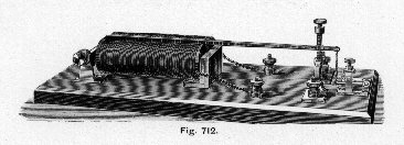
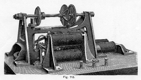
"The plan of Mr. Lane-Fox for distributing the currents from a central station to the incandescent lamps is illustrated in Fig. 711 where A A are a pair of generators driven by a steam engine as shown. One pole of each generator is connected to the prime conductor or 'electric main' C, and the other poles are connected to 'earth' by the earth plates E or water pipes. Branch conductors C1 C1 or submains start from the main, and other branch conductors C11 C11 lead to the lamps and through the lamps l l to the return main. The lamps are all in multiple arc, and a constant electromotive force of about 100 Volts is kept up in the circuit. To insure this result an automatic governor F, for controlling the generators is included in a circuit between the main and 'earth.' The regulator consists of an electro-magnet, through which a shunted portion of the current passes, and attracts a lever armature in front of its poles, as shown in Fig. 712. This lever plays between two adjustable contact pins resting midway when the current is of the proper intensity, but striking the upper pin if the current becomes too strong, and the lower pin if it becomes too weak. By this means a local circuit is closed, and more or less resistance is inserted in the circuit of the field magnets of the generator, so as to bring the lighting current to its normal value, and the lever of the regulator to its mid position. This resistance is inserted by the automatic device shown in Fig. 713, where the middle pair of electro-magnets are caused by the local current to rotate a vertical axis, carrying at its upper end a small toothed pinion, which can gear with either of the two like wheels, enclosing it between their toothed edges, as shown. If it gear with the right-hand wheel, the horizontal spindle carrying these two wheels will be rotated in one direction, and if it gear with the left-hand wheel the same spindle will be rotated in the other direction. Hence the second vertical axis seen on the left of the figure will be rotated in one direction or the other, and as it carries at its lower end a sliding contact arm which moves over the studs of a circular resistance box, partly visible in the figure, it throws in or takes out resistance from the field magnets. The direction in which the horizontal spindle shall turn is determined by two double electro-magnets, only parts of which are seen. According as the lever in Fig. 712 touches the upper or lower contact, one or other of these electro-magnets attracts an armature placed between their opposed poles, and brings the pinion-headed axis into gearing with one or other of the two wheels on the horizontal spindle.
"The secondary batteries B1 and B2 are used to store up any surplus current and return it to the circuits when there is any falling off in those below the normal current. At B1 they are arranged in 'series,' and at B2 they are so connected up by means of a commutator C, that the battery in discharging will automatically adapt the potential of its discharge to the needs of the mains as determined by the regulator E.
|

|
|
|
"The meters employed by Mr. Lane-Fox for measuring the current used in the lamps are of three kinds, one, in which a derived current from a supply conductor is passed through an electro-magnet and made, by attracting an armature, to open and close more or less a conical valve regulating the flow of air through a species of windmill counter. The other and preferable kind is illustrated in Fig. 714, where a is a similar electro-magnet in a derived circuit from the main, and c is the lever armature on its poles. The lever bears at its outer end on a spindle A, which is free to move vertically in a guide B, and forms a pivot for a spindle A1, which is supported by a spring C to keep the spindle A in contact with the lever armature. On the spindle A1 is a disc D in frictional contact with another disc E, which is driven by clockwork F, and pressed against D by a spring. On the same spindle is a long pinion G gearing with a toothed wheel H and actuating a counter. When no current passes in the electro-magnet a the disc D is exactly in the centre of E, and therefore does not rotate, but when the armature is attracted by a current the lever bearing on A displaces D from the centre of E and D begins to rotate with a speed proportional to its displacement, that is approximately proportional to the current strength. Thus the counter will indicate the quantity of current used.
|

|
"The meter chiefly used by Mr. Lane-Fox is, however, that shown in Fig. 715. It is an integrating meter, and consists of a double-poled electro-magnet wound with stout wire and having a hinged armature of soft iron inclined over it, as shown on the right of the figure. This armature is supported in its inclined position over the poles by a spiral spring hung from a striding support. The armature is branched at its extremity, and the fork is attached to a vertical stem seen on the left of the figure. This stem gears with a mechanical counter or indicator at its lower end as shown, and on its upper part carries a small horizontal disc which rolls on the rounded surface of a piece of boxwood, which is rotated round a vertical axis by means of a small oscillating electro-motor worked by a shunted portion of the main current. This piece of boxwood is of a semi-oval form, narrow at the top, so that when the horizontal disc touches at the upper parts it revolves less quickly than when it touches at the lower and thicker parts where the moving circumference of the boxwood is greater. And as the horizontal disc derives its rotation by frictional contact from the rotation of the boxwood surface, it follows that the position of the disc on the boxwood surface affects its rapidity of rotation, and consequently the indications of the counter. This position is altered by the strength of current in the main circuit passing through the doubled-poled electro-magnets. The attraction of this magnet pulls the armature down against the force of the spring, and with it the horizontal disc carried by the vertical stem. Further, the surface of the boxwood is turned to a curve, found by experiment to give the proper speed of indicator for the corresponding strength of current. The electro-motor, which gives a continuous rotation to the boxwood barrel, consists of two electro-magnets on a shunt circuit from the main current, and these by proper interrupting spring contacts are magnetised alternately, and keep a spring balance lever in oscillation. This lever in turn works a ratchet wheel, and rotates a shaft carrying the boxwood barrel. Clockwork could also be applied for this purpose, but the electro-motor requires no winding up.
"The Lane-Fox system is now worked by the Anglo-American Brush Electric Light Corporation, and was recently exhibited at the Crystal Palace, where the beautiful chandeliers designed by Mr. E. R. Johnson, for the Alhambra Courts, produced a very fine effect. These Courts were lit by Lane-Fox lamps fed from a Sellon-Volckmar secondary battery charged by a Brush machine, and the light was conveniently graduated by switching on a greater or less number of cells of the battery."
|

|
Regarding the design of the socket the following can be found in Dredge 7
"As in the Swan and Edison systems, so in the Brush system, the act of fixing the lamp in its holder or socket makes all the necessary electrical connections. The socket is convolvulus shaped, and is designed to fit the screw of an ordinary gas bracket at its lower end, while at its upper end its points or petals exert an elastic pressure upon the globe, preventing any vibration. The two leading wires are led up the centre of the holder, and are secured to two segmental curved springs fixed to a non-conducting plug in the body of the socket. When the lamp is dropped into position and rotated to lock the bayonet joint, the heads of its two terminal screws slide over the above-mentioned curved springs, forcing them down towards the plug, to which they are attached at one end, and making a good contact, which is rubbed clean every time the lamp is removed or inserted."
|

|
Regarding the design of the socket the following can be found in Dredge 7
There exists in the William J. Hammer Historical Collection of Incandescent Lamps (at the Ford Museum in Dearborn, Michigan), five Lane-Fox lamps 31. Four were made in 1881 and one in 1882. The identification numbers of these lamps are: 1881-81, 1881-93, 1881-95, 1881-96 and 1882-98. The descriptions are:
1881-81, early wooden base, vegetable filament, drilled carbon clamps, mercury sealed leads, tip exhaustion.
1881-93, 20 cp, side seal tipless lamp, vegetable filament, drilled carbon clamp, mercury sealed. Made by St. George Lane-Fox.
1881-95, small tipless side seal, vegetable filament lamp, drilled carbon clamps, mercury sealed arond leads.
1881-96, 20 cp, tipless, side seal bulb, vegetable filament, drilled carbon clamps, mercury sealed leads. Made by St. George Lane-Fox.
1882-98, 20 cp, 61-volt, vegetable filament lamp, drilled carbon clamps, mercury sealed around leads, tip sealed. Made by St. George Lane-Fox on Apr 22, 1882.
When it became clear to the general public that the development of a practical electric incandescent was "just around the corner" panic resulted because of the unknown effect this would have on the gas industry because so much lighting was being achieved through the use of gas. Lane-Fox addressed this question in a letter to the editor of a newspaper1.
The inventor Charles F. Brush entered into the life of Lane-Fox in the year 1880. On Dec 12 1879, the Anglo American Electric Light Company Limited was formed in England in an effort to acquire the patent rights of Charles Brush29,30. Also, in 1879 this new company bought the patent rights to manufacture Lane-Fox incandescent lamps. However, the company was short-lived. A new company, called the Anglo-American Brush Electric Light Corporation, was formed on Mar 24 1880. This new company took over the earlier one and then extended its operation. In the United States, Charles Brush tested Lane-Fox lamps (on Jun 9 1884) and found them to be unsatisfactory. Brush (actually the Swan Lamp Manufacturing Company) then adopted the Swan lamp to manufacture, starting in 1885. Swan lamps had been manufactured by the Swan Incandescent Electric Light Company of New York since 1882. However starting in 1885 the manufacturing was carried on solely by a licensee, the Swan Lamp Manufacturing Company of Cleveland. The Cleveland Company manufactured lamps for ten years. In 1897 the New York Company applied to the Supreme Court for voluntary dissolution of the company. The testing and rejection of Lane-Fox lamps by Brush probably accelerated the demise of their manufacture.
It should be emphasized that St. George Lane Fox-Pitt was a very young man during his work with the incandescent lamp. His patent activities started about 1878 and appear to have ended about 1883. Having been born in the year 1856 he was therefore about 22 to 27 years of age during these activities. By any standard it must be concluded that he was contributing at a very early age to a developing industry. It appears that A. A. Campbell Swinton was also impressed with the work output of Fox-Pitt at such an early age19. Swinton said:
"...he had undoubtedly had a very remarkable youth, as three years earlier, in 1876, he had applied an electric ignition device of his own invention to the gas lamps of Pall Mall."
In the year 1881 Colonel R.E. Crompton presented a paper titled: "The Progress of the Electric Light"5. Several comments were made by individuals at the conclusion of the lecture. One discussion was by St. George Lane-Fox. A part of what he had to say follows:
"I believe that Mr. Edison...has really done a very great deal for this subject. ...I think great credit is due to him for having stated from the very first that it was possible to introduce a system of electric lighting that could be so distributed and divided as to be available for household purposes. I think Mr. Edison was the first, and not Mr. Swan, to produce a practically useful lamp on the incandescent principle, with a filament of carbon in a vacuum. Mr. Edison's researches too in respect to the presence of occluded gases in metals and other substances, are exceedingly interesting and very sound and scientific in the manner he has carried them out. I think he has rendered very great service not only to the future of electric lighting, but also to science, by his investigations, and for this proper credit should be given to him, more especially as in the future he will be able to show, and I have no doubt he will show, that he was the first to succeed, and I think it is as well to recognize it at once. I say this entirely disinterestedly, because it is very much to my disadvantage that Mr. Edison should be first, as I have also claims in this direction..."
It is of interest to read some of what Francis Jehl, associate of Thomas Alva Edison, had to say about Lane-Fox 21:
"St. George Lane-Fox was a British scientist, philosopher, inventor and experimenter. Contemporaneously with Edison he attempted to solve the problem of domestic lighting and, like Edison, knew what the characteristics of such a lamp should be. However, he did not succeed in making the lamp and was too honest and upright to start or enter into any nefarious scheme or plot in an attempt to rob Edison of his birthright.
"Edison once said that he thought Lane-Fox would beat him, but it did not happen, for the trail that Edison followed was different from the trail that Lane-Fox pursued. Although Lane-Fox had patents and claims, yet this nobleman considered honor and justice above all. Disinterestedly, he publicly asserted that Edison was the first to make a practical lamp and that his discovery of the presence of occluded gases rendered very great service to science and to the future of electric lighting, and that it is well to recognize it at once."
After his work with the incandescent lamp, which probably stopped about 1883, scant information regarding the life of St. George Lane Fox-Pitt could be found. Some information was obtained from Bowden's book 29, as well as the book written about St. George's sister, Agnes 27; in addition, a few facts emerge regarding the whereabouts and activities of St. George in the biography of Helena Petrovna Hahn Blavatsky (1831-1891) 26. In his autobiography Bertrand Russell 24 devoted two pages to a discussion of the Pitt-Rivers family. Bertrand Russell (1872-1970) was the son of Katherine, younger sister of Alice Margaret Stanley, wife of Augustus 29. Russell was, therefore, a first cousin to St. George Lane Fox-Pitt. Although this writer has not seen the works, it is believed that at least two additional articles by Fox-Pitt can be found in the literature 16,17. He also wrote a book on the purpose of education18. Apparently Fox-Pitt married Lady Edith Douglas in the spring of 1899 13.
An obituary appeared in The Times (London) at the time of Fox-Pitt's death20. The following was taken verbatim:
"Mr. Fox Pitt - Inventor and Psychic Student
"Mr. St. George Lane Fox Pitt, who died suddenly yesterday at his residence in South Eaton-place at the age of 75, was a pioneer of electric lighting, a student of psychic phenomena, and an advocate of moral education.
"Mr. Fox Pitt was the second son of Lieutenant-General Augustus Henry Lane Fox Pitt-Rivers, D.C.L., F.R.S., of Rushmore, Wilts, who was of the family of Lane Fox, of Bramham Park, Yorkshire, and who took the surname of Pitt-Rivers for himself and that of Pitt for his issue. General Pitt-Rivers was the distinguished anthropologist and archaeologist who presented his collection to the University of Oxford. He married Alice, daughter of the second Lord Stanley of Alderly, and one of his daughters married his fellow archaeologist, the first Lord Avebury.
"Born at Malta on September 14, 1856, Fox Pitt devoted himself in early manhood to scientific research and mechanical inventions. He invented the Lane-Fox system of electric lighting and distribution, taking out one of the earliest patents (1878) for the use of small incandescent lamps in parallel; was one of the first active workers in the Society of Psychical Research; was vice-president and treasurer of the Moral Eduacation League and organizer of the International Moral Education Congress; and wrote a number of books on science philosophy, education, and social problems. He also fought three elections in the Liberal interest, but without success. In a discourse at the Royal Institution as far back as 1912 the late Mr. Campbell Swinton said that Fox Pitt was 'the first person to imagine, or at any rate to patent, a public electricity supply to all and sundry.'
"In a contribution to a book entitled 'Spiritualism: Its Present Day Meaning,' published in 1920, Fox Pitt explained his view that the proposition of an unchangeable and independent 'ego' and its survival was simply unmeaning; an immutable 'psychic body' was simply unmeaning; an immutable 'psychic body' was a pernicious delusion. 'Materializations' were not more than evanescent phenomena. The craving for 'egoistic survival,' in contradistinction to individual continuity, was a very strong one, and in his view was at the root of all evil. He agreed with Bergson that 'supernormal psychic phenomena' were always in operation, though generally speaking unnoticed.
"He married in 1899 Lady Edith Douglas, daughter of the eighth Marquess of Queensberry. The funeral will be at Golders Green Crematorium on Saturday at 11:30."
Acknowledgements
The writer is grateful to Eunice Grauper, librarian at the University of Wisconsin-Madison and Bruce A. Hanesalo at Military/Info for valuable information. I also thank Mark Bowden for suggestions that led to desired biographical information. A letter from G. A. Lane-Fox Pitt-Rivers was most helpful in pointing out an important reference the writer had overlooked. Marie Lampert at the British Library was a source for patent numbers. The Humanities Reference Service at the British Library provided a write-up that was informative.
|
Patents
- GB 1878-3988 - Oct 9, 1878 - Electric Lighting
- GB 1878-4043 - Oct 12, 1878 - Applied Electricity for Lighting and Heating
- GB 1878-4626 - Nov 14, 1878 - Electric Lighting
- GB 1879-1122 - Mar 20, 1879 - Electric Light
- GB 1880-3494 - Aug 28, 1880 - Electric Lamps
- GB 1881-225 - Jan 18, 1881 - Electric lamps
- GB 1881-1543 - Apr 8, 1881 - Electric lamps
- GB 1881-1636 - Apr 14, 1881 - Apparatus for Producing Motion by Electricity
- GB 1881-3122 - Jul 18, 1881 - Electric Bridges for Lamps
- GB 1881-3394 - Aug 5, 1881 - Generating Electric Currents
- GB 1881-4383 - Oct 8, 1881 - Electric Bridges for Incandescent Lamps
- GB 1881-5651 - Dec 24, 1881 - Electric Current Meters
- GB 1882-1647 - Apr 5, 1882 - Manufacture of Incandescent Electric Lamps
- GB 1882-4625 - 1882 - Secondary Batteries
- GB 1883-56 - 1883 - Measuring Electric Currents
- GB 1883-3692 - 1883 - Electrical Distribution
References
- "Letter to the Editor", St. George Lane-Fox, The Times (London), Dec 26 1878, p.3.
- "On the Application of Electricity to Lighting and Heating, and for Domestic and Other Purposes", St. George Lane Fox Pitt, Journal of the Society of Telegraph Engineers, Vol.10, 1881, pp.148-155.
- "Electric Illumination", Vol.1, Cooke, Dredge, O'Reilly and Thompson, Offices of "Engineering", London, 1882, pp.647-658.
- "The Future of Electric Lighting", St. George Lane-Fox, Journal of the Royal United Service Institution, (Ordinance Notes - No.249, Washington, Feb 17 1883; copy available from Military/Info. See website: http://www.military-info.com/Aphoto/Subjectlist/A039.htm). The specific volume in the J. of the R. U. S. I. is not known. The writer's best guesses for the year are 1880, 1881 or 1882.
- "The Progress of the Electric Light", R. E. Crompton, Journal of the Royal United Service Institution, (Ordinance Notes - No.287, Washington, Apr 11 1883; copy available from Military/Info. See website: http://www.military-info.com/Aphoto/Subjectlist/A039.htm). The specific volume in the J. of the R. U. S. I. is not known but it might be Vol 25, 1882, pg 82-.
- "The Electric Light: Its History, Production and Applications", Alglave, E. & J. Boulard, (translation by T. O. Sloane), D. Appleton & Co., New York, 1884, pp.177-.
- "Electric Illumination", Vol.2, Dredge, O'Reilly and Vivarez, Offices of "Engineering," London, 1885, pp.319-320.
- "Arc and Glow Lamps-A Practical Handbook on Electric Lighting", Julius Maier, Whittaker & Co., London, 1886, pp.284-287.
- The Electrical Engineer, Vol.11, Jun 10 1891, p.662.
- The Electrical Engineer, Vol.12, Jul 14 1891, p.77.
- The Electrical Engineer, Vol.14, Oct 4 1892, p.333.
- The Electrical Engineer, Vol.15, Feb 22 1893, p.189.
- "Memoirs of the Moment", The Academy, Vol.56, Jan 21 1899, p. 99. Announcement of the coming marriage of Mr. St. George Lane Fox-Pitt and Lady Edith Douglas.
- "Incandescent Lamp Development to the Year 1880, III", Edwin W. Hammer, Electrical World and Engineer, Vol.36 No.24, Dec 15 1900, pp.918-919.
- "An Index to Changes of Name, 1760-1901", compiled by W. P. W. Phillimore and Edw. Alex. Fry, London, Phillimore & Co., 124, Chancery Lane, London, 1905, p.120.
- ""The Subliminal Mind"", Lane Fox-Pitt, Occult Review, Vol.1, Apr 1905, p.168.
- "Self", St George Lane Fox-Pitt, Occult Review, Vol.2, Aug 1905, p.55.
- "The Purpose of Education - An Examination of Educational Problems in the Light of Recent Scientific Research", St. George Lane Fox Pitt, Cambridge University Press, 1925.
- "The Part Played by Mr. St. George Lane Fox Pitt in the Invention of the Carbon Incandescent Electric Lamp, and the Modern Method of Electric Lighting," A. A. Campbell Swinton, Journal of the Institution of Electrical Engineers, Vol.67, 1929, pp.551-552.
- "Obituary, St. George Lane Fox Pitt", The Times (London), Apr 7 1932, p.14.
- "Menlo Park Reminiscences, Vol.2, Francis Jehl, The Edison Institute, Dearborn, Michigan, 1938, p.482.
- "The Electric-Lamp Industry: Technological Change and Economic Development from 1800 to 1947", Arthur A. Bright Jr, The Macmillan Co., New York, 1949, pp.49-50.
- "The Distribution and Utilization of Electricity", C. Mackechnie Jarvis, A History of Technology, Vol.5, The Late Nineteenth Century (c.1850 to c .1900), Oxford at the Clarendon Press, 1958, pp.215-219.
- "The Autobiography of Bertrand Russell (1872-1914)", Little, Brown & Co., Boston, 1967, pp.213-214.
- "Augustus Henry Lane Fox Pitt-Rivers", Dictionary of Scientific Biography, Vol.XI, 1975, Charles Scribner's Sons, New York, pp.5-6.
- "Madame Blavatsky - The Woman Behind the Myth", Marion Meade, G. P. Putnam's Sons, New York, 1980.
- "Concerning Agnes - Thomas Hardy's 'Good Little Pupil'", Desmond Hawkins, Alan Sutton Publishing Ltd., Gloucester, 1982.
- "The History of N. V. Philips' Gloeilampenfabrieken", Vol.1, The Origin of the Dutch Incandescent Lamp Industry, A. Heerding, Cambridge University Press, London, 1985.
- "Pitt Rivers - The Life and Archaeological Work of Lieutenant-General Augustus Henry Lane Fox Pitt Rivers, DCL, FRS, FSA", Mark Bowden, Cambridge University Press, Cambridge, 1991.
- "What's In A Class 60 Name", George Toms, Brush Transport Enthusiasts Club, 1992.
- "The William J. Hammer Historical Collection of Incandescent Electric lamps", E.J. Covington (archived page)
|
|
|
|
|


